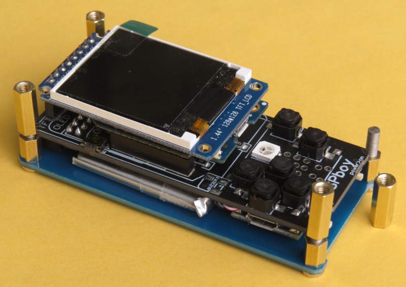
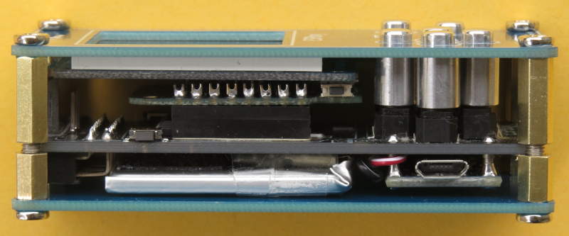
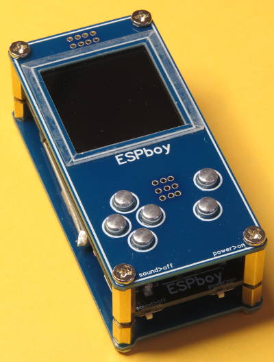
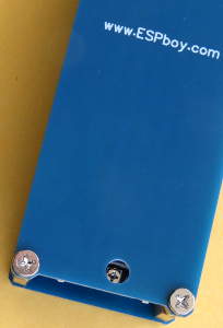
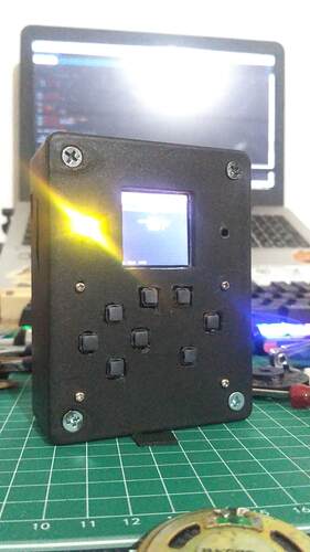
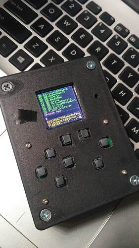
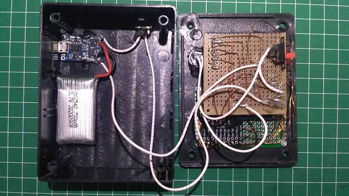
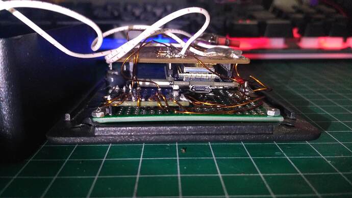
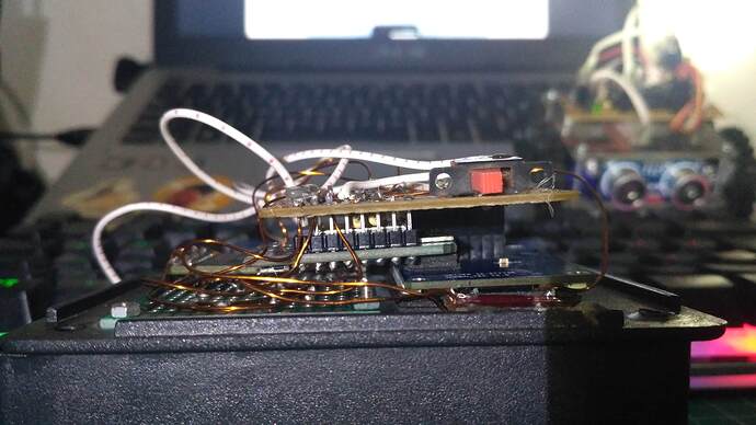
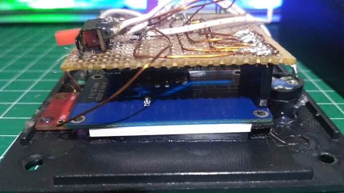
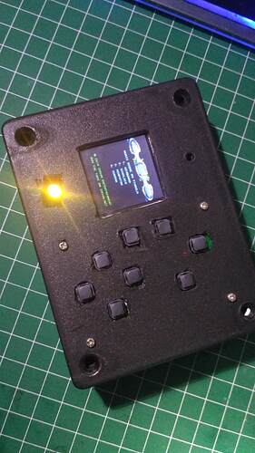
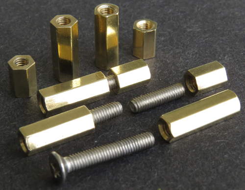
I could have just used longer standoffs but I didn’t like the way the main board “floats” between the front and back panels, with it being prevented from moving up and down only because the assembly thickness exactly matches the length of the supplied standoffs. Instead, I used larger diameter standoffs with an M3 thread. I had some 15mm ones that I cut to two lengths to provide the proper spacing needed between the main board and the front and back panels. For each corner the standoffs are joined by threaded studs made by cutting long M3 screws. (It would have been better to use a male-female standoff for one of the lengths, or long round head screws to hold the standoffs to both one panel and the other standoff, but I didn’t have any on hand.)
The original standoffs are 3mm wide, which matches the diameter of an M3 screw, so by leaving a gap between the joined standoffs, the main board is held by its corners, the same as originally designed, but now it’s also held an exact distance between the front and back panels.
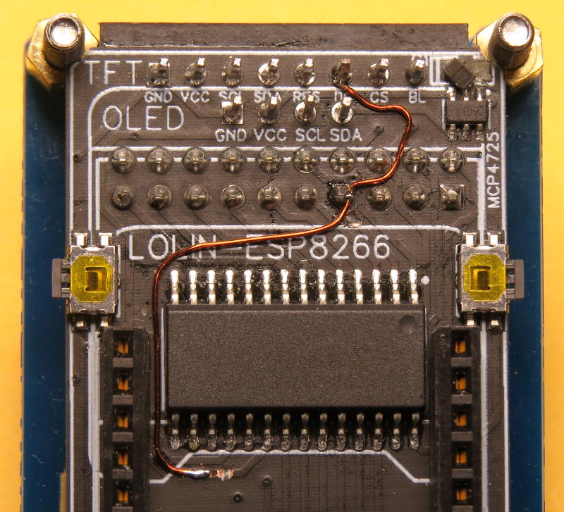
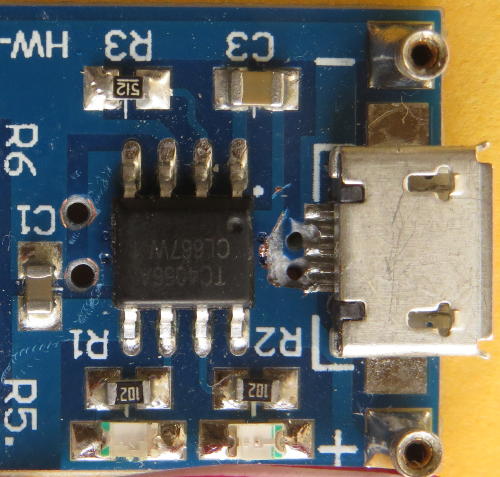
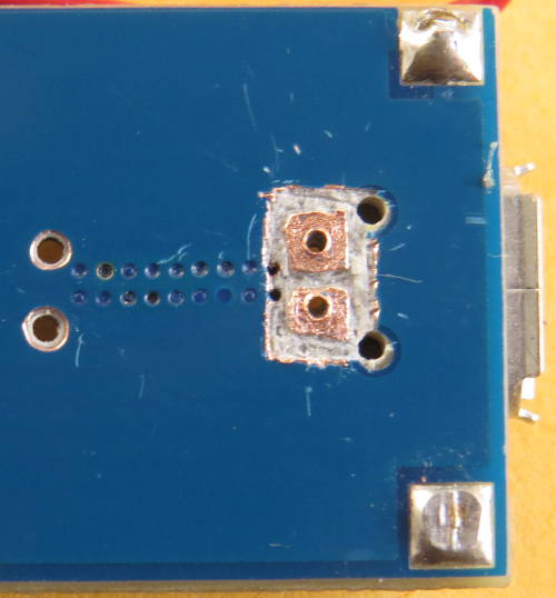
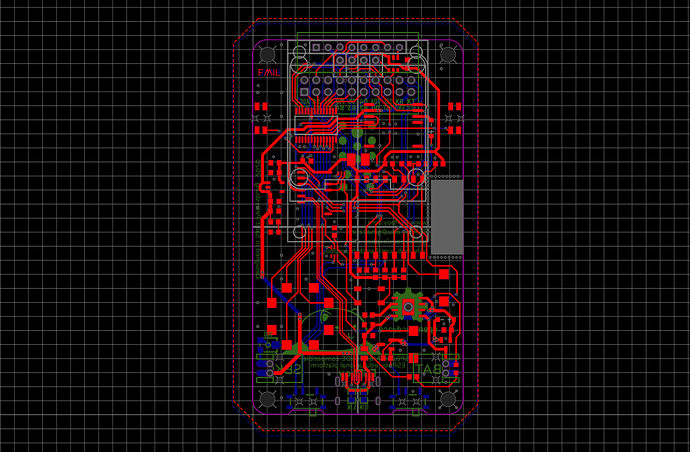
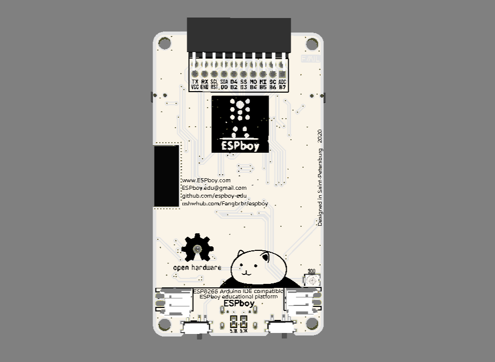
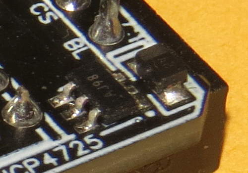
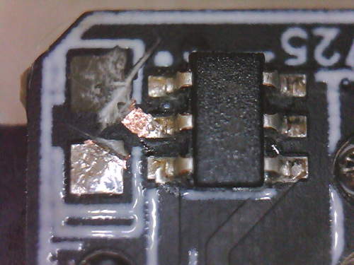
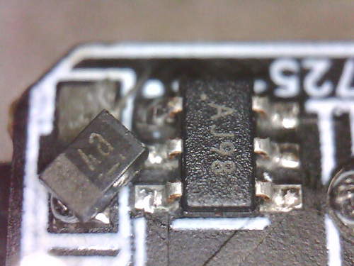
One problem I encountered is that capacitor C1 is very close to the upper right corner of the main board, so it interfered with the larger diameter standoff. To fix this, I removed C1 and then cut and peeled off the circuit board pad closest to the corner, and cut a notch in the other pad for clearance. I then scraped off the solder mask over the trace coming from the removed pad to form a new pad. This allowed me to re-install C1 at an angle with clearance from the corner.
The top corners of the display also interfered with the wider standoffs, so I cut notches to provide clearance. And, of course, the mounting holes in the corners of the front and back panels had to be drilled larger to accept M3 size screws.
Since with my unit the distance from the main board to the front panel is longer, I couldn’t use the provided screws, springs and nuts to activate the buttons. Besides, I didn’t really like this design.
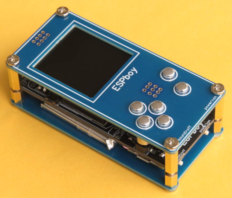
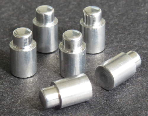
To allow the buttons to be operated from the front panel, I made button extenders from ¼ inch (6mm) round aluminium bar stock. I enlarged the holes in the front panel for the buttons to a diameter suitable for a button (about 4.5 mm). For each extender, I cut down the diameter at one end to match the panel hole, with a length that allows it go through the hole and be able to press the button. I rounded and polished this end. The rest of the extender is cut to the exact distance between the inside of the panel and the top of the unpressed button.
I’m very pleased with how the extenders look and feel. 
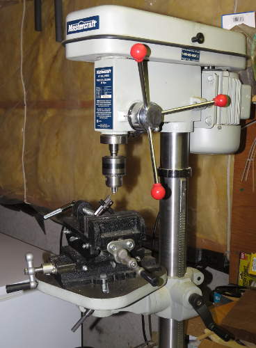
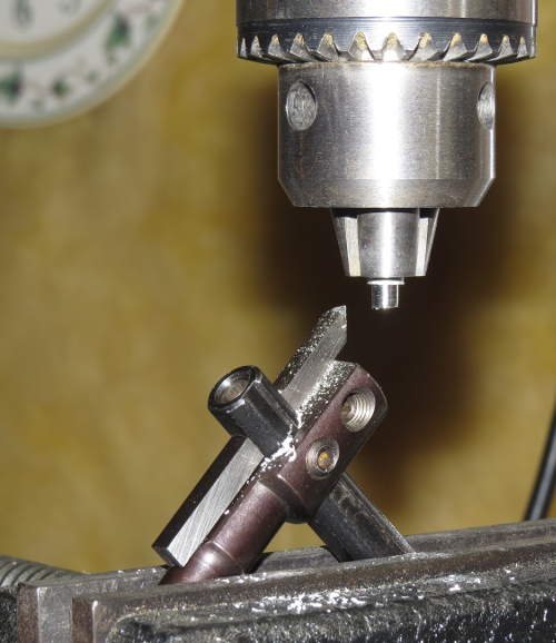
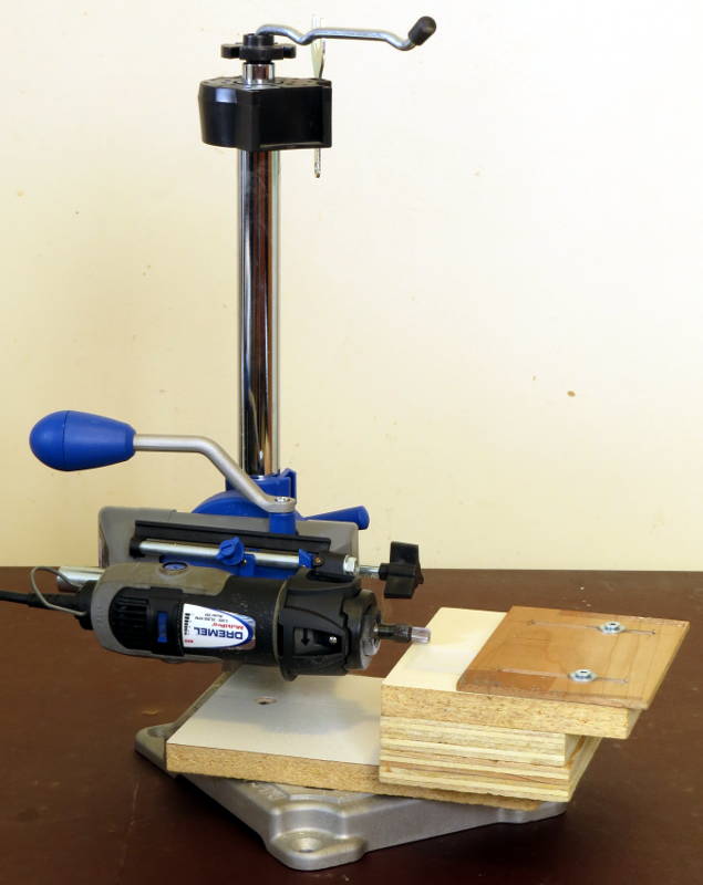
I don’t have a lathe, so I had to improvise a way to cut down the diameter of the button extenders. I used my drill press, along with my cross slide vise with an adjustable circle cutter clamped in as a cutting bit. It took a bit of time to devise and set up but worked well once I figured it all out. 
