Nice. Well done. Just an idea, but maybe you could make a rotation of your screen to have it in face with a rotation 0 to avoid to change all codes ?
It’s maybe too late but i think it’s could be easier to change it now than to make all needed to have your own app store. Else Roman have put source online for the client here: https://github.com/ESPboy-edu/ESPboy_OTA but i don’t think that server configuration is explained somewhere (maybe i just missed it).
Welcome and have fun 
2 Likes
Thanks for your advice, but sadly it is actually too late. It is not just simply rotate the screen. My screen just fit perfectly right now. If I rotate the screen I must desolder all the connection from mcp23017 to wemos D1 mini since they are in the different protoboard and the wire is pretty short. Maybe I will just enjoy my espboy clone without OTA downloader. 
2 Likes
First of all, I have to say that ESPboy is a super project. I always think that ESP8266 is a module with great potential. But beside me, many people just use AT command to control ESP8266 as a network transmission tool. I think this is a waste of this powerful module. Of course, I can also think of why ESP8266 is not used much because it has too few pins. . and it’s really a great idea to use MCP23017 to extend the pin position.
I don’t have a D1mini board, but the Schematic of this board’s circuit is very detailed on the network. So I set out to build the entire circuit on a single PCB. I happen to have the ESP8266 module and the CH340 chip and a few other components here. So I think it’s doable.
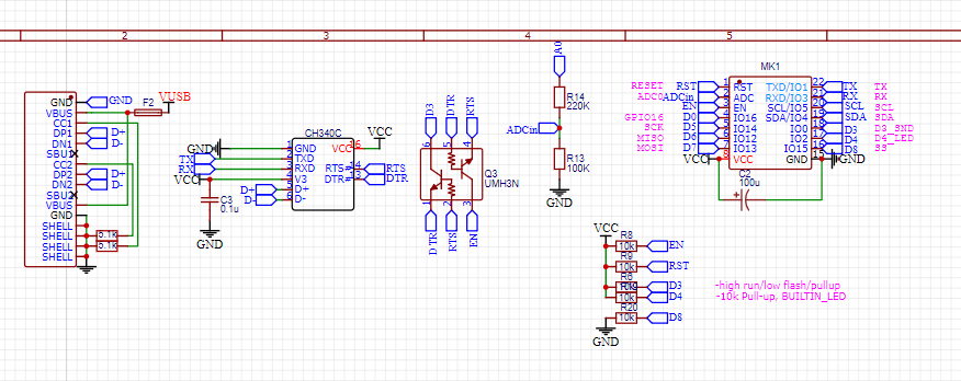
The picture above shows a typical ESP8266 extension circuit that I have used in other projects and works well.
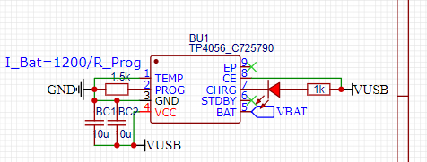
Similarly, the li-battery charging module based on TP4056 is also rich in data and easy to make.We can draw them directly and share a USB port with the ESP8266 circuit.
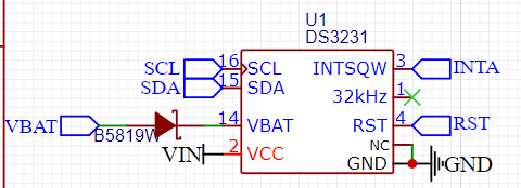
When I found the MCP23017 chip using the SSOP package , there was still a lot of space on this PCB, so I chose to add an IIC device to the IIC bus—DS3231 real-time clock.This also reflects the advantages of the IIC bus.
When I put these ideas together, I found that the real difficulty lies in wiring… After I arranged the components, the flying leads looked really complicated.

I am not very familiar with the protocol requirements of open source hardware. so I have put the original logo and text in.
After a lot of effort, I finally connected all the wires, and the final result of the simulation image looks not bad.
I like to make some cartoon graphics on the PCB, I don’t know if this is allowed for open source hardware😅…
I have just finished drawing the PCB,
If there is no problem, then you should prepare to make PCB and buy missing components and,
try do make one .
4 Likes
Your PCB ended up to be very similar to the ESPboy2 PCB except the ESPboy2 uses just a bare display soldered directly to the board, instead of a display module.
2 Likes
wow, that sounds should be cool, I think with the way the entire row female connector makes espboy very thick, I now have some new ideas, I think I can improve the look of my PCB😋。
thank u very much MLXXXp
2 Likes
Hello everyone, I’m here again.
Today I brought my first completed espboy.

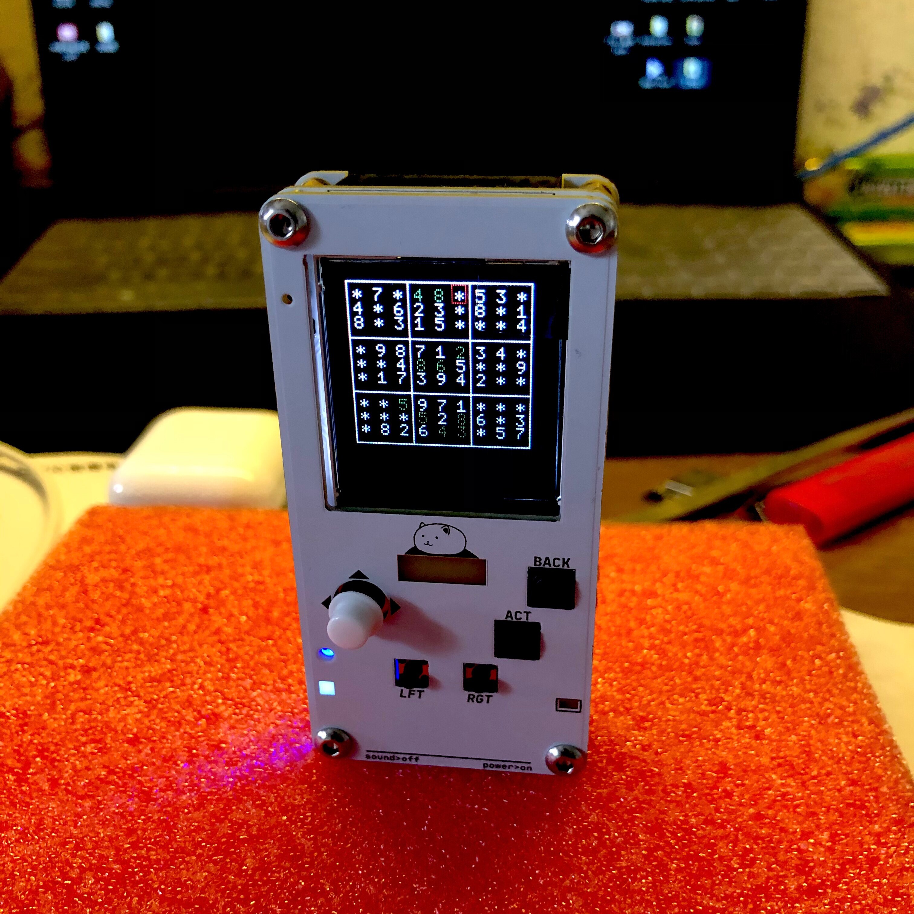
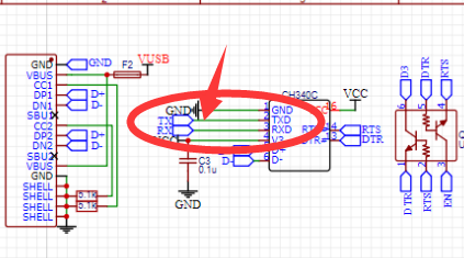
First I need to correct a schematic error that I posted before.The two wires of the serial port need to be cross-connected
Then my PCB design integrates three circuit layers and makes them all at once.
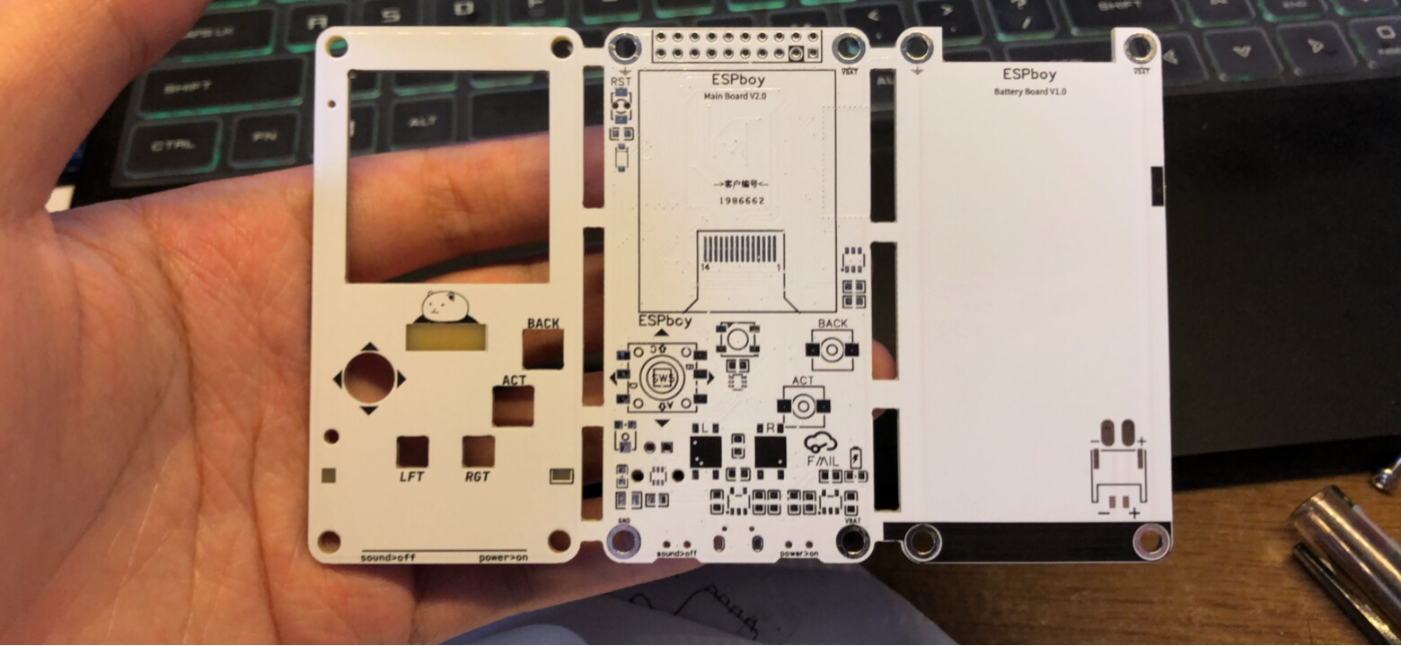
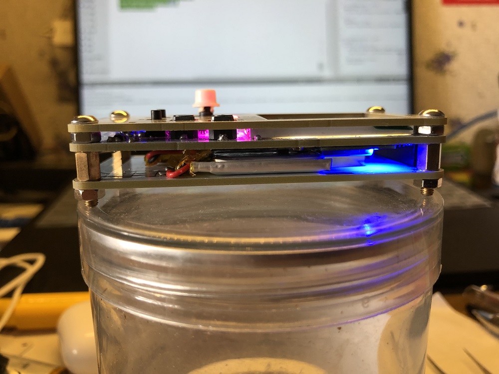
Then break it apart and polish the edges to get three boards, namely the front board , the main board and the battery board.
The main board is used for the main part, all components except the battery are on the main board; and the battery is connected to the battery board and is connected to the main board through copper nut to provide power.

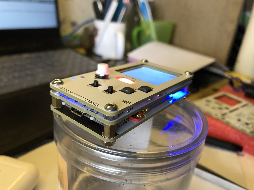

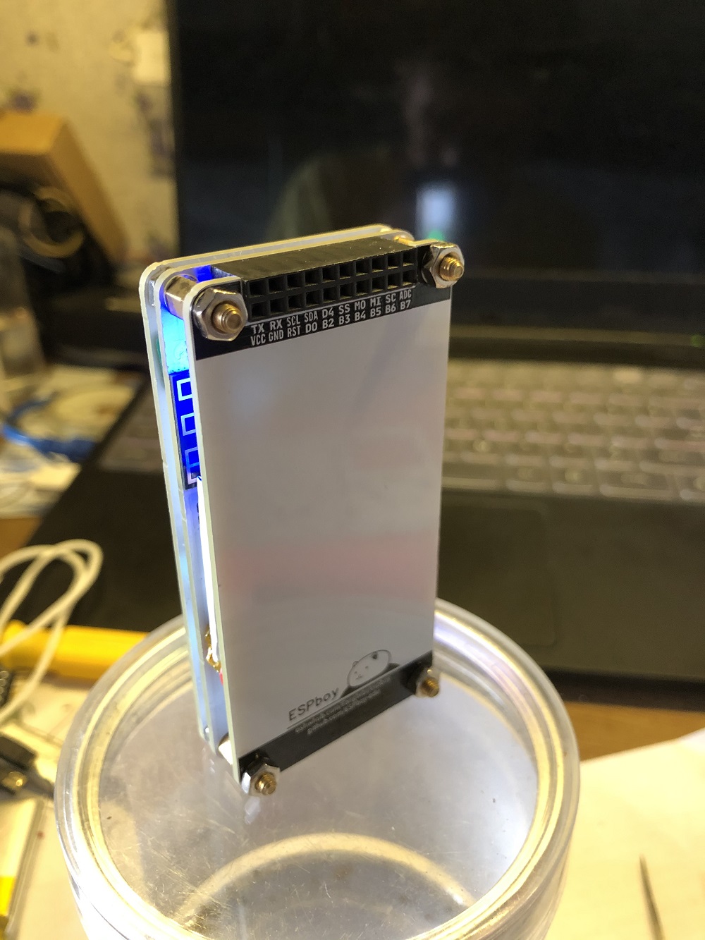
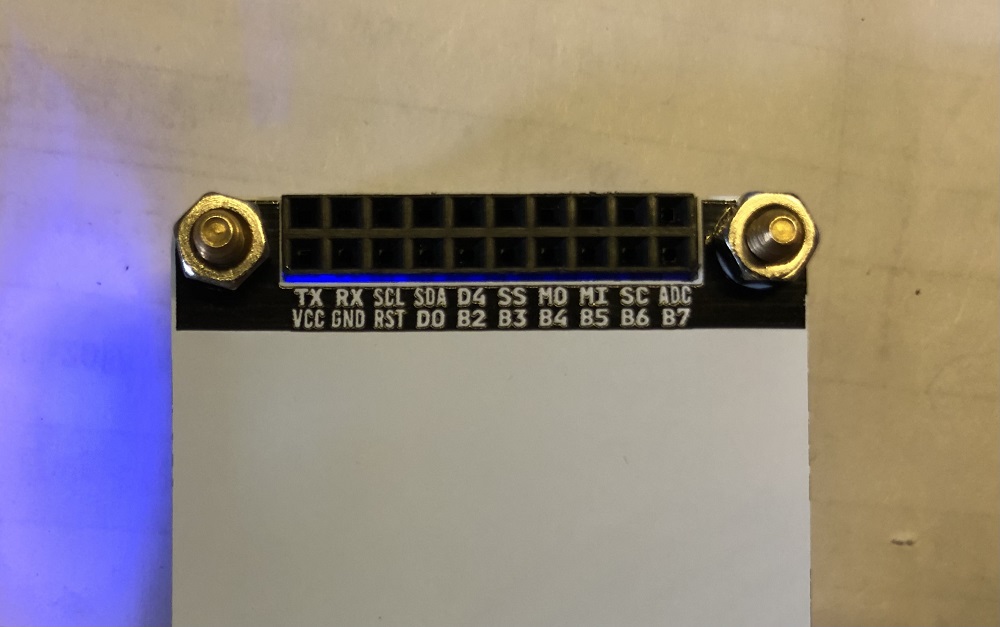
I used ordinary headers for the expansion port, and its direction is backward. No shortcomings have been found so far, because I don’t have any expansion modules to use.
There is a usb port at the bottom, which can be used for battery charging and program download。
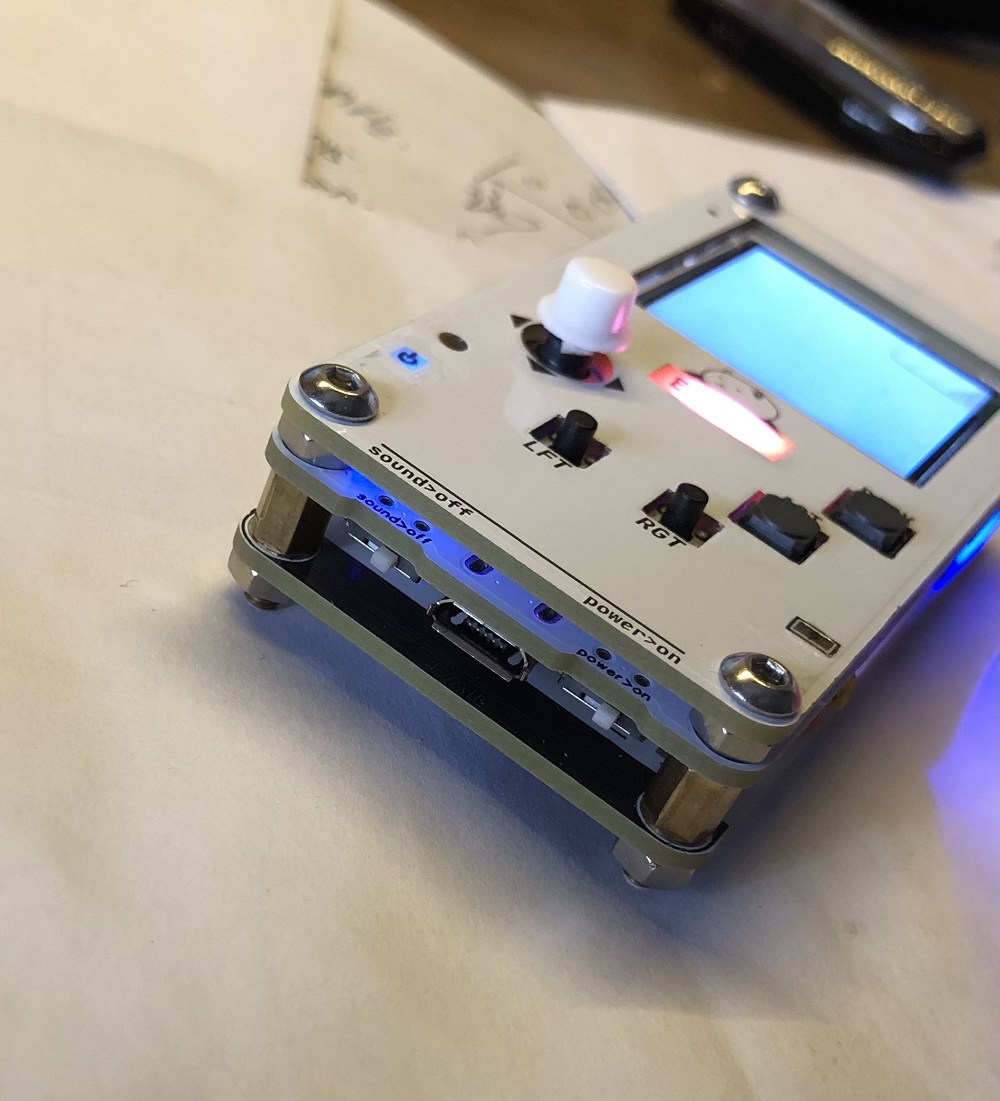
The most expensive one is the screen, but I am very happy to make it in the end.
actually, the battery connection method is bad, because the nuts are exposed, I accidentally put it on the metal plane, causing irreversible damage to the battery.
3 Likes
Nice. well done and welcome on board
1 Like
Looks great! Perfect work ) Does it connects to AppSore as well?
1 Like
Thank you 
Thank you for all the work you do for ESPBOY and for sharing it with us.
I do have a problem connecting to the AppStore,
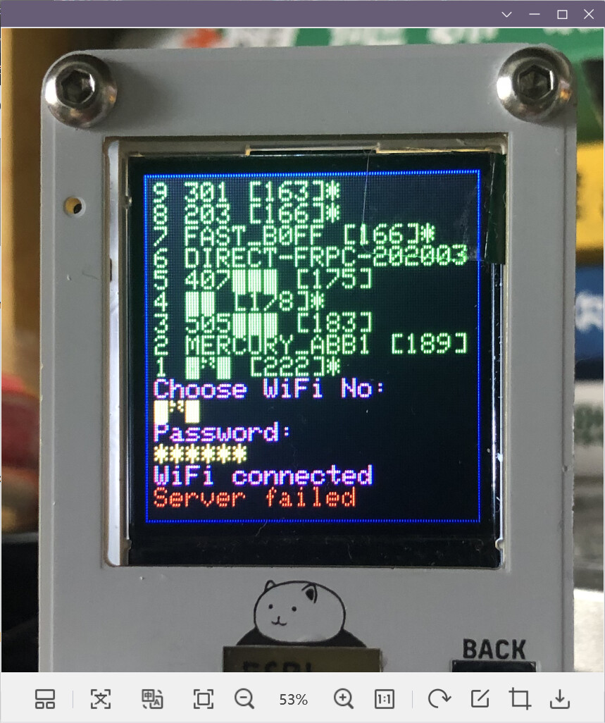
When I connect to WiFi using ESP8266, wait for a while, it will show Server Failed. Switching other WiFi signals doesn’t work either.
Therefore, I can only connect the computer to the AP created by ESP8266 and upload the APP through the web page.
I think it’s because I’m in China
It’s too far. 
I suppose you are using OTA1, not OTA2. The reason why it should be - blocking google services in China which are used by ESPboy AppStore (
2 Likes
Oh, this is indeed the reason.
And it seems that there is no way to solve it 
Yeah, otherwise you have to keep it on one setting but it’s good to be able to change it whenever you want.
Boge you don’t waste time to everyone but yes. MLXXXp: or Roman have alot to do too and want help people to let them advance but they can’t answer to all questions because they don’t have alot of time. So i understand MLXXXp:, first you have to search by yourself and focalize on one thing. You have all components list. Fine. Now, when it’s will arrive, construct your own system with only required function and try it to confirm it’s works and continue to advance step by step. Then you’ll be able to ask questions and have new answers. ATM, you could even forgert answers before be able to use them and / or maybe some things will change since this time (i don’t think but it’s always possible).
So for me, wait for your hardware make a first version as easy as you can or with all things you know and test then ask required questions to let continue to advance if needed.
2 Likes
@Boge
A few rules of life for a very young person:
- Keep the discussion on the topic mostly according to the topic (In this thread, we are happy to see the version of ESPboy built by @Boge and other people)

- People around have a lot of different things to do.
- People around you don’t owe you anything.
- If someone has at least a few seconds to help - this is a great success and you should learn to be grateful to fate and to this person.
- No one will do something for you for a long time and will not receive anything in return, so you need to figure out how to thank a person for his time, knowledge, attention and help.
- Politeness, perseverance, and patience will help you reach many heights.
4 Likes
Thank you this is so kind ![]()
2 Likes
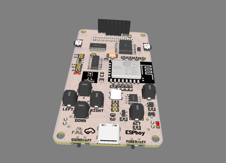
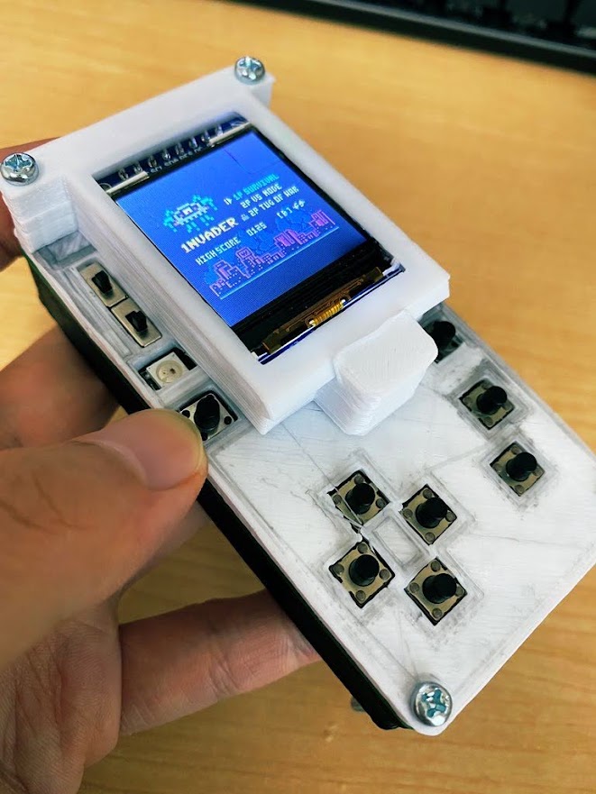
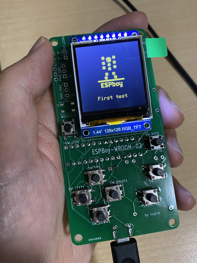
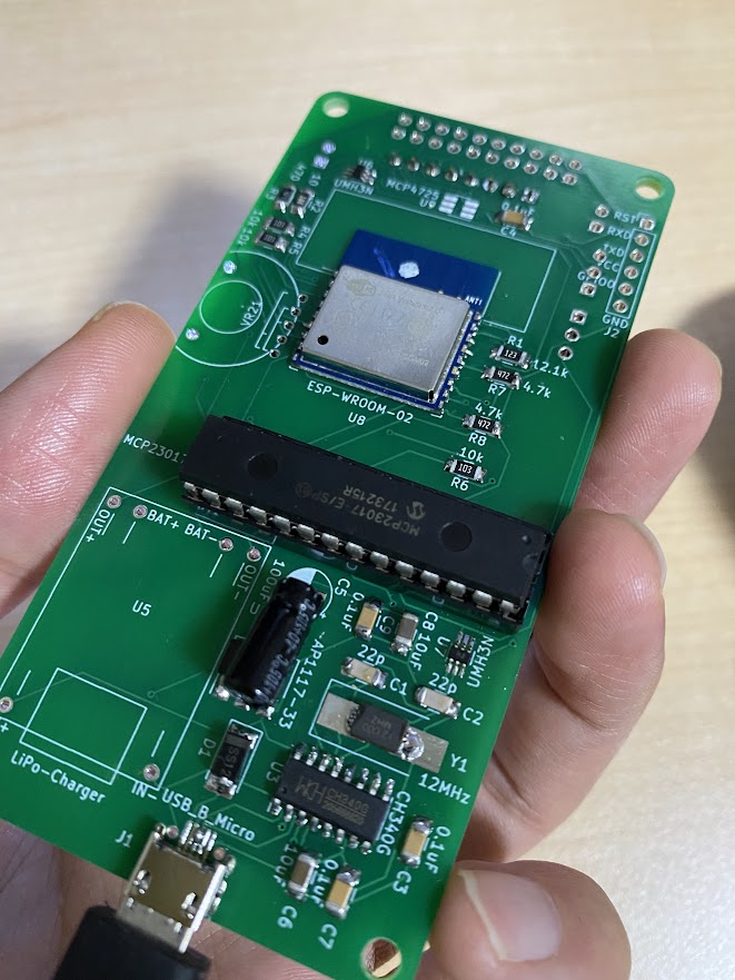
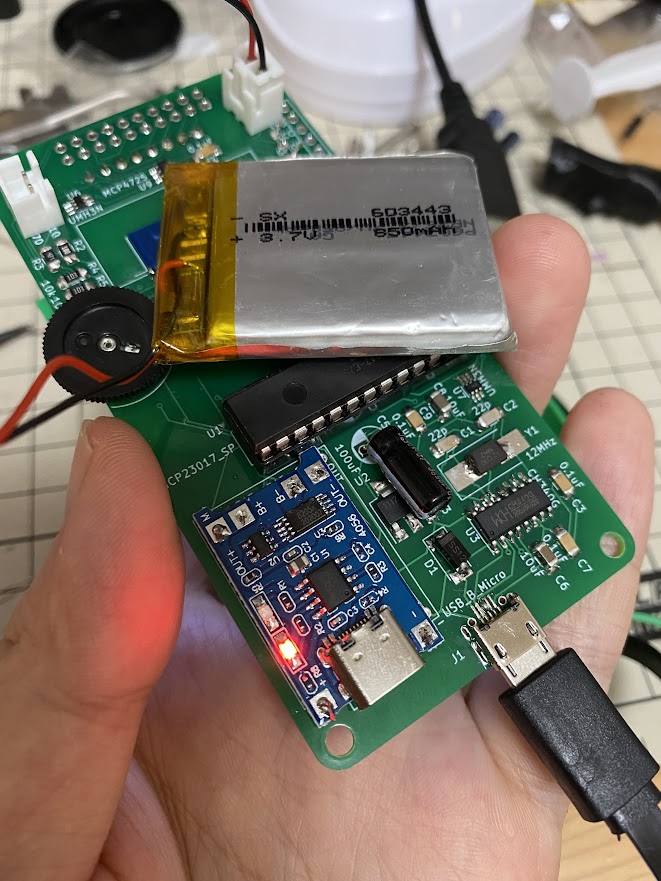
Hello, I made ESPboy by ESP-WROOM-02.
In Japan a wireless communication module is limited by a law. So almost all ESP8266 module must not use in Japan.
I found ESP-WROOM-02 which certified by TELEC which can use in Japan.
So I began to make my ESPboy by ESP-WOOM-02.
This ESPboy seems to be 100% compatible in original ESPboy.
I wrote an article to introduce my ESPboy. (in Japanese)
https://inajob.hatenablog.jp/entry/espboy
7 Likes
Great approach and wonderful interpretation of the original design.
I wonder if your version of the device works well when downloading apps from the WebAppStore?
And how well do apps from the standard ESPboy AppStore work?
Yes.
My DIY ESPboy seems be compatible to original one.
2 Likes