Hi,
I am trying to build a ESPBoy with minimal configuration. My main focus is to play the games and develop new games. I’ll skip using the header for peripheral HW addon for now.
I am thinking of the following -
High impedence speaker to be connected to D3 of ESP8266 through a 10uf polar cap and a 47 ohm register in series (No transistor amp).
Din of WS2812 to be connected to D4 of EDP8266 through 470 ohm.
I found 128x164 TFT display (ST7735). Hence there will be 36px unused. I’ll use it in portrait mode. Thinking of putting battery level indicator and clock in this unused 36px. (I believe slight modification in SW can achieve that.)
I think for my purpose of the gadget, I can fully remove MCP2317. Instead voltage devider ladder can be used to get different ADC value for different combination of switch press. getKey() function can be overriden to read analog from A0.
For display Led brightness control, could we use a GPIO to deliver PWM?
(MCP4725 is unavailable in my region)
Yes, so many changes. As my primary intention is to play the games, I was thinking of those changes. Another thing is, not all parts are available in my region. Anyway, good news for me is I could collected an MCP2317. But still, I cant collect MCP4725.
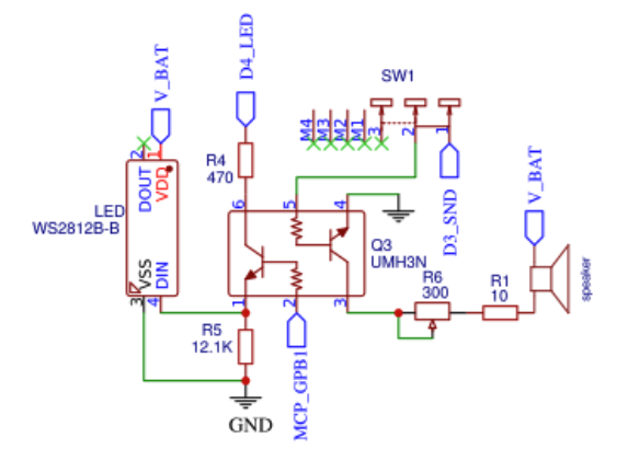
Can I simplify the WS2812 circuit as such, MCP_GPB1 is directly connected to Din of WS2812 through a resistor?
The MCP4725 controls the brightness of the display’s backlight. I don’t think this is being used much, if at all, so you can just permanently power the display backlight directly, so it’s always on at full brightness. If it’s to bright for you when powered directly, you can add a fixed resistor in series to lower the brightness. You could also use a potentiometer, so that you could control the brightness manually.
The WS2812 RGB LED is not associated with the MCP4725.
WS2812 is controlled by a Transistor which is controlled by D4 of MCU and MCP_GPB1 of MCP2317. I guess one of these (D4 and MCP_GPB1) is for data and the other is for enabling data of WS2812. So I was thinking if I can skip the enabling function, and keep the data only.
Yes, you can do that. The enabling function was just for problems with one of the modules that plugs into the expansion connector. Since you’re not adding the expansion connector, you shouldn’t need to disable the WS2812 DIN.
Looks like you are building some kind of custom device that will not be software compatible with ESPboy )
When you build your own gadget you can use any parts and components, it is of course a fun and interesting process, but it will not be easy to find all the answers, mostly it will require a lot of experimentation.
But we already went that way, so you can just build a standard ESPboy with the simplest possible circuit ) ESPboy building instructions