ESPboy DIY heroes welcome! )

The next ESPboy hero - Pavel is a translator and philosopher.
No soldering experience at all but kit was assembled after 2 hours with help of tenacity, patience and 200 grams of Irish whiskey.

Congrat, Pavel!

1 Like

For my ESPboy, I wanted to be able to easily disconnect all the modules. Here’s what I did to assemble my kit:

For the WeMos D1 Mini board I used pins removed from a DIP header. For matching sockets on the main board I cut and separated the two sides of a 16 pin DIP socket.

ESPboy-01

ESPboy-02

The included battery was too long to fit in the space provided. However, the battery includes a small circuit board for protection. The same protection circuitry (using a DW01 IC and a dual MOSFET) is included on the charger board. The board in the battery is redundant, so not required.

I removed the board from the battery and bent the battery terminals back. This shortened the battery so it would fit. (The welds connecting the battery terminal tabs to the protection board weren’t very strong and they broke off).

The metal used for the battery terminals can’t be soldered to. I found some small spade connectors that fit the terminals properly. I removed the plastic insulator, soldered wires to them, cut them shorter and covered them with heat shrink tubing, with the wire coming out of the same end as the connector opening. On the other end of the wires I put pins from male and female round machined pin headers, then covered them with heat shrink.

ESPboy-03

For the charger board, I used machined pins removed from a wirewrap DIP socket. I increased the size of the holes on the board, so the pins could be inserted deeper into the board, to reduce the overall height. I attached wires with machined pins to connect to the battery wires.

I used strong clear tape to hold the battery connectors firmly in place. To attach the battery to the main board, I used a piece of Velcro.

ESPboy-04

ESPboy-05

ESPboy-06

On the main board I put individual male header pins for attaching the display. I also added the 4 pins for an OLED display, just in case. On the display I used a standard size female header strip.

I put round header pins, cut short, on the main board to connect to the sockets on the charger board. I put a matching piece of Velcro on the main board for the battery.

The speaker is positioned a bit off centre so that the TC4056A IC on the charger board, which is thicker than the other components, won’t interfere with the speaker. (However, the battery assembly ended up higher than I expected it to be, so I could have just soldered the charger board pins higher.)

Since my ESPboy assembly is thicker than standard, I have to come up with a way of mounting the front and back panels, and extending the buttons. I’ll post about that when I’m done.

1 Like

I could have just used longer standoffs but I didn’t like the way the main board “floats” between the front and back panels, with it being prevented from moving up and down only because the assembly thickness exactly matches the length of the supplied standoffs. Instead, I used larger diameter standoffs with an M3 thread. I had some 15mm ones that I cut to two lengths to provide the proper spacing needed between the main board and the front and back panels. For each corner the standoffs are joined by threaded studs made by cutting long M3 screws. (It would have been better to use a male-female standoff for one of the lengths, or long round head screws to hold the standoffs to both one panel and the other standoff, but I didn’t have any on hand.)

The original standoffs are 3mm wide, which matches the diameter of an M3 screw, so by leaving a gap between the joined standoffs, the main board is held by its corners, the same as originally designed, but now it’s also held an exact distance between the front and back panels.

ESPboy-20

One problem I encountered is that capacitor C1 is very close to the upper right corner of the main board, so it interfered with the larger diameter standoff. To fix this, I removed C1 and then cut and peeled off the circuit board pad closest to the corner, and cut a notch in the other pad for clearance. I then scraped off the solder mask over the trace coming from the removed pad to form a new pad. This allowed me to re-install C1 at an angle with clearance from the corner.

ESPboy-21

ESPboy-22

ESPboy-23

The top corners of the display also interfered with the wider standoffs, so I cut notches to provide clearance. And, of course, the mounting holes in the corners of the front and back panels had to be drilled larger to accept M3 size screws.

Since with my unit the distance from the main board to the front panel is longer, I couldn’t use the provided screws, springs and nuts to activate the buttons. Besides, I didn’t really like this design.

To allow the buttons to be operated from the front panel, I made button extenders from ¼ inch (6mm) round aluminium bar stock. I enlarged the holes in the front panel for the buttons to a diameter suitable for a button (about 4.5 mm). For each extender, I cut down the diameter at one end to match the panel hole, with a length that allows it go through the hole and be able to press the button. I rounded and polished this end. The rest of the extender is cut to the exact distance between the inside of the panel and the top of the unpressed button.

I’m very pleased with how the extenders look and feel. :smiley:

ESPboy-25

I don’t have a lathe, so I had to improvise a way to cut down the diameter of the button extenders. I used my drill press, along with my cross slide vise with an adjustable circle cutter clamped in as a cutting bit. It took a bit of time to devise and set up but worked well once I figured it all out. :hammer_and_wrench:

ESPboy-28

2 Likes

I didn’t like that the display is exposed through the front panel. I kept getting fingerprints on it and was afraid it might get scratched or broken. So, I made a cover out of 2mm thick clear acrylic. I machined shoulders on the edges so that about half the thickness of the cover is recessed into panel opening. (I made some similar covers for a few more devices at the same time.)

The cover is held on using double sided tape. Because the machined surface is a bit rough, the edges look a bit blotchy but it’s not too bad.

ESPboy-30

To machine the acrylic, I made a feed table out of scrap wood to use with my Dremel rotary tool with a 115 carving bit, attached to the workstation accessory.

2 Likes

On my V3.2 board, I changed control of the LCD DC signal from D8(15) to D0(16), to match the current hardware revision V3.7:

  • Cut trace on bottom layer from expansion header pin 12 to LCD DC. The trace is mostly under the header but I was able to scratch it open just above the solder pad using a sewing needle.

  • Cut trace on top layer from MCP23017 pin 2 (GPB1) to expansion header pin 7.

  • Cut trace on top layer from D0(16) to MCP23017 pin 20 (INTA), leaving enough of the trace from the D0(16) side to solder a wire to.

  • Add wire on top layer from D0(16) trace to header pin 7 to LCD DC.

ESPboy-40

1 Like

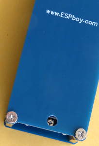
I drilled a hole in the back panel over the potentiometer, so I can adjust the speaker volume without removing the panel. Maybe do this for production?

ESPboy-50

2 Likes

Here is my perf board version following the original circuit.
But I simplified the speaker a bit to just connect the output (GPIO 0) through a 10uF Capacitor to a 10K variable resistor then to the buzzer.

4 Likes

Excellent!
But it’s better to use GPIO0 for LCD DC pin and D3 for sound to provide compatibility with all the original ESPboy software and AppStore )

UPD:

UPD2&3:
Effects of Varying I2C Pull-Up Resistors

1 Like

Here the video of my DIY perf board version of ESPBoy.
With volume control and headphone jack (added after the video).
using MCP23017 GPIO0 for LCD DC pin and D3 for sound.

4 Likes

5 posts were split to a new topic: Wiring a display with a different pinout

Hello everyone! Here is my assembly of ESPboy, the speaker did not find a small one to stick on. Quite a nimble toy turned out. Special thanks for helping Roman.


Not a working speaker is soldered in the photo))) I attach the video:

5 Likes

ding to this scheme:

1 Like

I made one more change to my ESPboy: I wired the data pins on the battery charger board’s micro-USB connector to the D1 mini board. Now I can use the charger USB port for both charging and data connections. I no longer have to remove the top cover to connect to the D1 mini’s USB.

On the charger board, I drilled two small holes close to the USB connector D+ and D- pins. The holes are drilled at an angle, so they’re wider apart on the other side of the board. I cut away some of the copper around the pins and holes to make soldering to the pins easier, with less risk of shorts. I also drilled two larger holes close to the centre of the board for a string to be used as a strain relief for the wires.

ESPboy-60

On the other side of the charger board I cut the copper and scraped off the solder mask to make two pads to solder the wires to.

For each stranded wire, I kept two of the strands long and passed them through the hole. The remaining short strands are soldered to the pads. I used black sewing thread in the centre holes to hold the wires and put some glue on the knot to prevent it from coming loose. I soldered two pins from a round pin socket header strip on the other ends of the wires as a connector.

ESPboy-62

The longer wire strands that went though the holes are soldered to the USB connector pins.

ESPboy-63

I soldered wires to the D+ and D- pins of the USB serial chip on the D1 mini and put two pins from a round pin header strip on the other ends.

ESPboy-64

The pins are plugged into the sockets and then everything is reassembled.

ESPboy-65

ESPboy-66

2 Likes

It’s amazing mod! I thing i’ll try to make it standard solution for all future ESPboys as well )

3 Likes

Hello everyone! Recently I completed the creation of an espboy clone) For me, the consoles are only convenient in horizontal projection, so i decided to do just that. I used the minimum number of components:

5 Likes

Amazing DIY clone!
Later you can add the RGB led and mcp4725 DAC module to control LCD backlit.
These details are standard ESPboy features )

2 Likes

Thank you! In the near future, I hope there will be time for this)

2 Likes

Hello everyone!, Here is my espboy clone. I am interested to make it look like gameboy console, so I made the shell from universal project box since I have no access to any 3d printer.

(the hole for the button is not perfect but it does its job)

The disturbing black tape on the left of the screen is to reduce the RGB LED light. Actually it is transparent vinyl sticker so the light can pass through. I should stick it from the inside. Now it looks so ugly. On the right side I made a hole for buzzer sound.

Here is the inside. I made two hole for charging port and power switch in the body. The Red switch is connected to buzzer and wemos D3 pin. I don’t know why, when the buzzer is connected to D3 when uploading the code, it always failed and it said “esptool.FatalError: Failed to connect to ESP8266: Timed out waiting for packet header”. So, I decided using switch to disconnect the buzzer when programming.

(a view from bottom side)
Currently I have to remove front panel from the box for programming. In the future I’m interested to change the connection like @MLXXXp did.

(a view from right side)

(a view from top side)
I decided to place the screen landscape since I know the TFT LCD orientation can be rotated simply with only change the tft.setRotation(0); to tft.setRotation(3);. But then I realize that it doesn’t work with OTA programmer since all the programs in the “appstore” are using default orientation : tft.setRotation(0);. I wonder if I can edit my own “appstore” and edit all the screen rotation to match my espboy clone.

Here is the example after uploading from “appstore” :

2 Likes

Nice. Well done. Just an idea, but maybe you could make a rotation of your screen to have it in face with a rotation 0 to avoid to change all codes ?
It’s maybe too late but i think it’s could be easier to change it now than to make all needed to have your own app store. Else Roman have put source online for the client here: https://github.com/ESPboy-edu/ESPboy_OTA but i don’t think that server configuration is explained somewhere (maybe i just missed it).
Welcome and have fun :slight_smile:

2 Likes

Thanks for your advice, but sadly it is actually too late. It is not just simply rotate the screen. My screen just fit perfectly right now. If I rotate the screen I must desolder all the connection from mcp23017 to wemos D1 mini since they are in the different protoboard and the wire is pretty short. Maybe I will just enjoy my espboy clone without OTA downloader. :smiley:

2 Likes