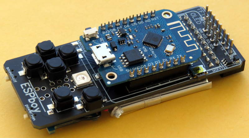
For my ESPboy, I wanted to be able to easily disconnect all the modules. Here’s what I did to assemble my kit:
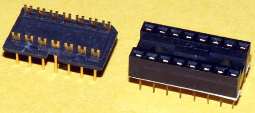
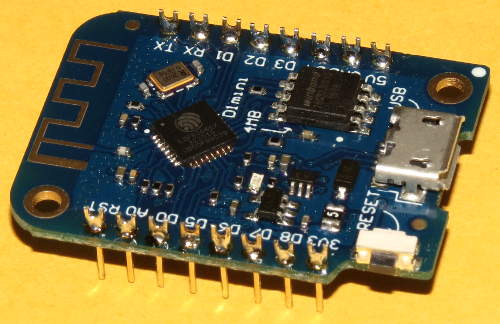
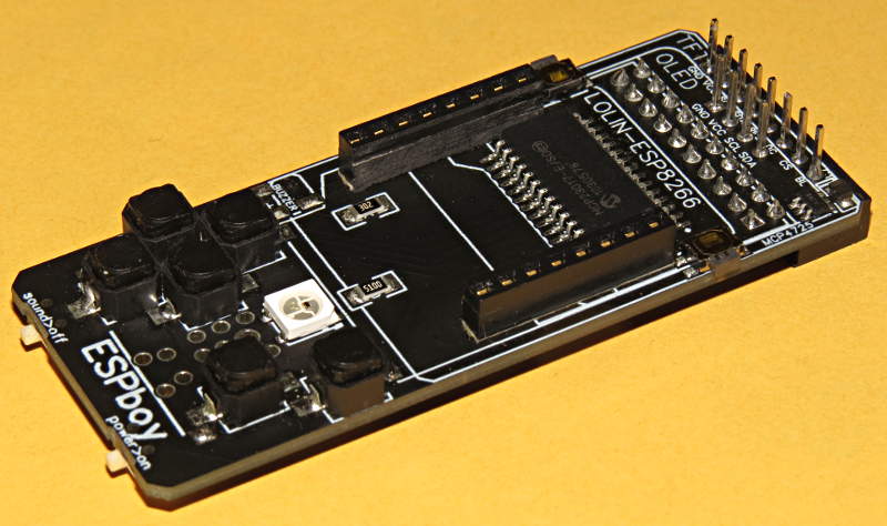
For the WeMos D1 Mini board I used pins removed from a DIP header. For matching sockets on the main board I cut and separated the two sides of a 16 pin DIP socket.
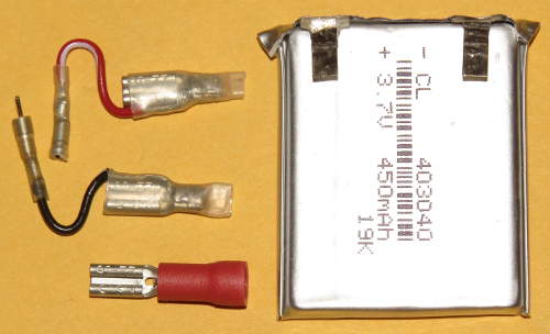
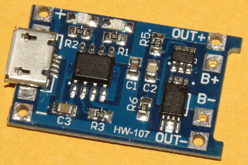
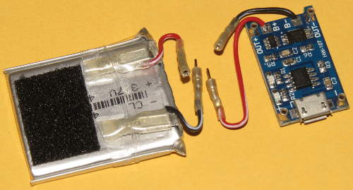
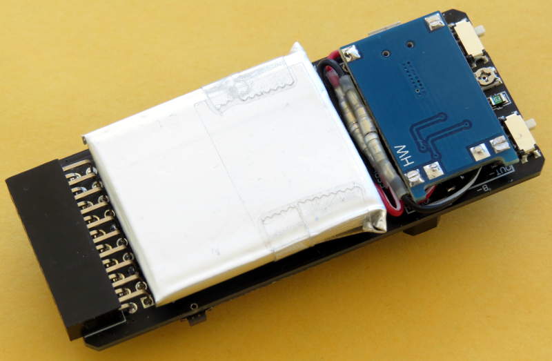
The included battery was too long to fit in the space provided. However, the battery includes a small circuit board for protection. The same protection circuitry (using a DW01 IC and a dual MOSFET) is included on the charger board. The board in the battery is redundant, so not required.
I removed the board from the battery and bent the battery terminals back. This shortened the battery so it would fit. (The welds connecting the battery terminal tabs to the protection board weren’t very strong and they broke off).
The metal used for the battery terminals can’t be soldered to. I found some small spade connectors that fit the terminals properly. I removed the plastic insulator, soldered wires to them, cut them shorter and covered them with heat shrink tubing, with the wire coming out of the same end as the connector opening. On the other end of the wires I put pins from male and female round machined pin headers, then covered them with heat shrink.
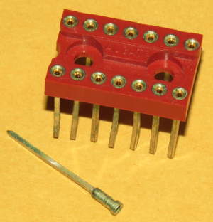
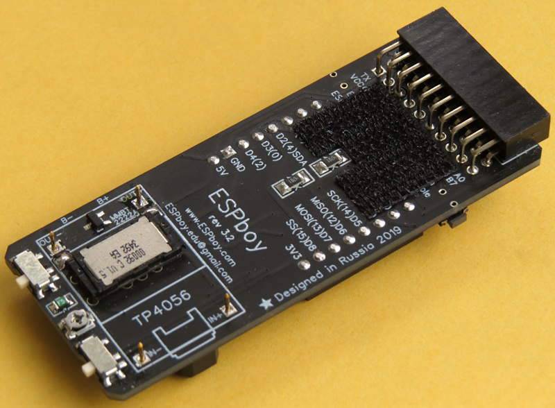
For the charger board, I used machined pins removed from a wirewrap DIP socket. I increased the size of the holes on the board, so the pins could be inserted deeper into the board, to reduce the overall height. I attached wires with machined pins to connect to the battery wires.
I used strong clear tape to hold the battery connectors firmly in place. To attach the battery to the main board, I used a piece of Velcro.
On the main board I put individual male header pins for attaching the display. I also added the 4 pins for an OLED display, just in case. On the display I used a standard size female header strip.
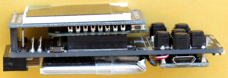
I put round header pins, cut short, on the main board to connect to the sockets on the charger board. I put a matching piece of Velcro on the main board for the battery.
The speaker is positioned a bit off centre so that the TC4056A IC on the charger board, which is thicker than the other components, won’t interfere with the speaker. (However, the battery assembly ended up higher than I expected it to be, so I could have just soldered the charger board pins higher.)

Since my ESPboy assembly is thicker than standard, I have to come up with a way of mounting the front and back panels, and extending the buttons. I’ll post about that when I’m done.