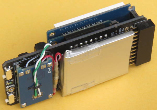
I made one more change to my ESPboy: I wired the data pins on the battery charger board’s micro-USB connector to the D1 mini board. Now I can use the charger USB port for both charging and data connections. I no longer have to remove the top cover to connect to the D1 mini’s USB.
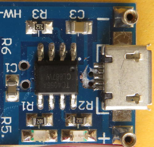
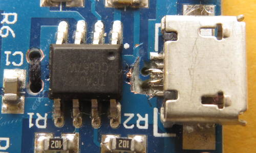
On the charger board, I drilled two small holes close to the USB connector D+ and D- pins. The holes are drilled at an angle, so they’re wider apart on the other side of the board. I cut away some of the copper around the pins and holes to make soldering to the pins easier, with less risk of shorts. I also drilled two larger holes close to the centre of the board for a string to be used as a strain relief for the wires.
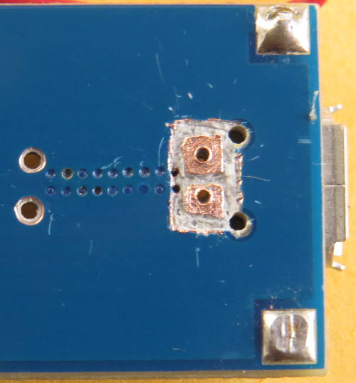
On the other side of the charger board I cut the copper and scraped off the solder mask to make two pads to solder the wires to.
For each stranded wire, I kept two of the strands long and passed them through the hole. The remaining short strands are soldered to the pads. I used black sewing thread in the centre holes to hold the wires and put some glue on the knot to prevent it from coming loose. I soldered two pins from a round pin socket header strip on the other ends of the wires as a connector.
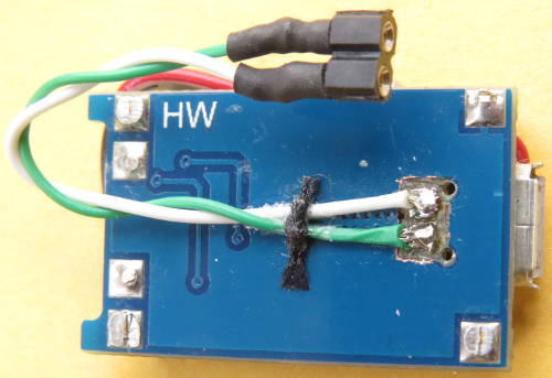
The longer wire strands that went though the holes are soldered to the USB connector pins.
I soldered wires to the D+ and D- pins of the USB serial chip on the D1 mini and put two pins from a round pin header strip on the other ends.
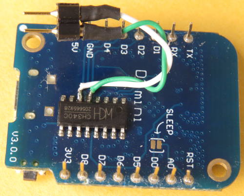
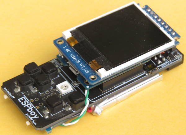
The pins are plugged into the sockets and then everything is reassembled.