There have been complaints that ESPboy1 is hard to build for beginners and of course that’s my fault, I got carried away with compactness and SMD.
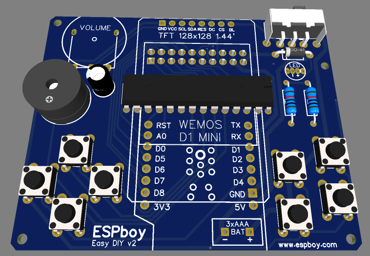
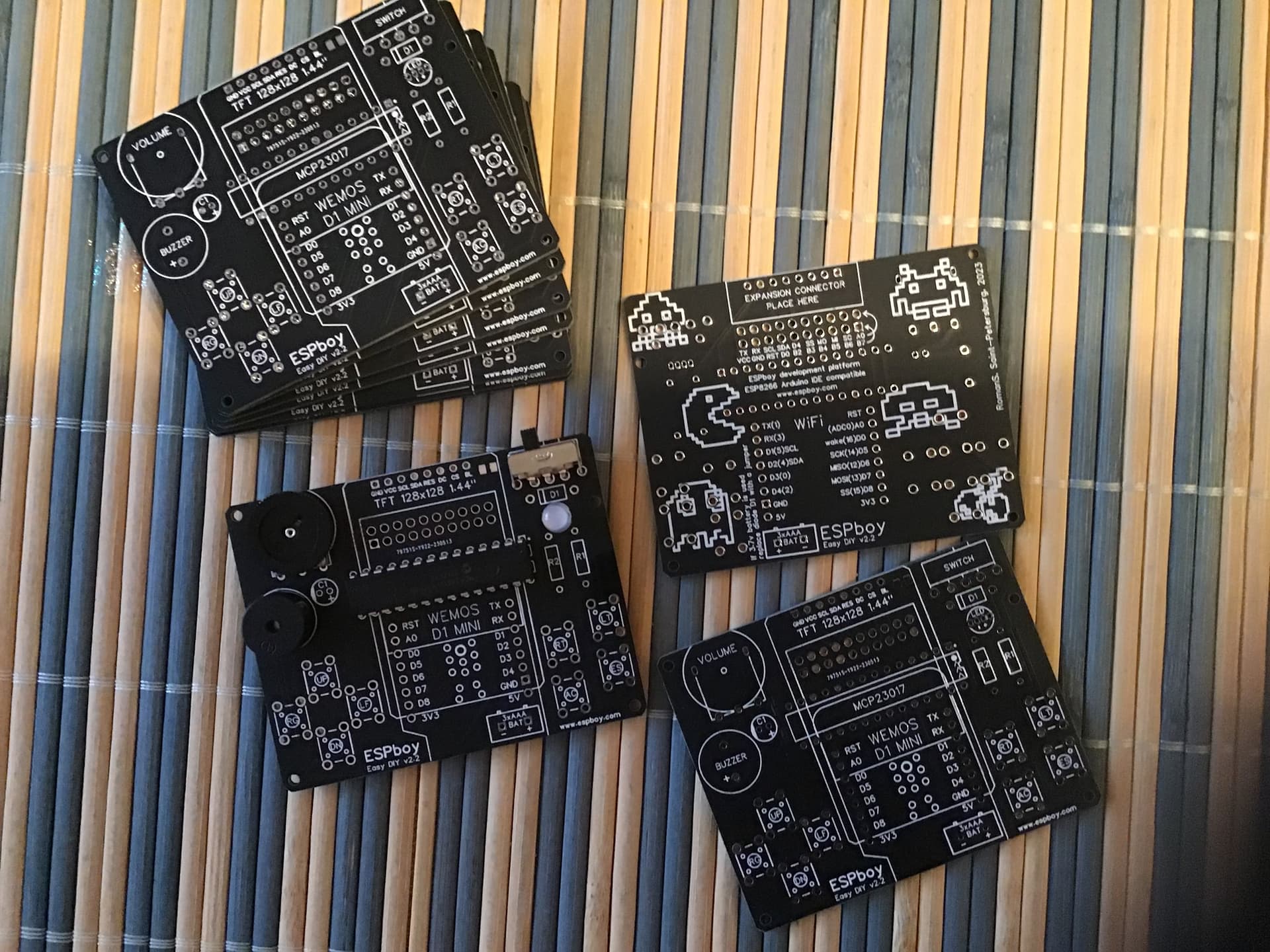
But now I decided to go back to the source and finished a simplified circuit on large and cheap through-holes components.
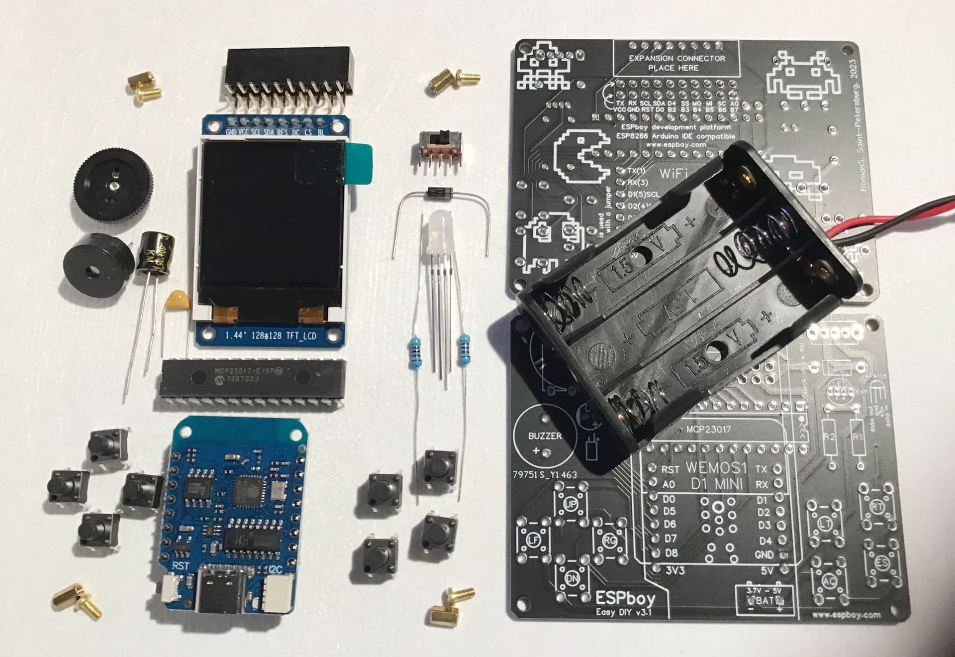
Now you can buy all a few parts for less than $10 and even a kid can solder them.
It’s very hard to go wrong.
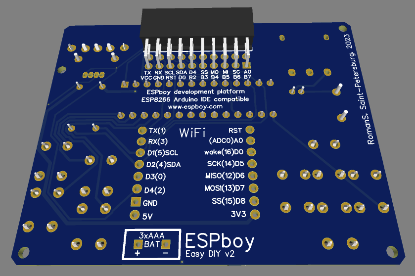
The compatibility to ESPboy1/ESPboy2 is 99.9% and an extension slot is provided.
So even on this simple device is available ESPboy AppStore, WebAppStore and in general all software and extension modules of the standard ESPboy.
Thanks to @MLXXXp for helping me design and the whole community for their support and inspiration
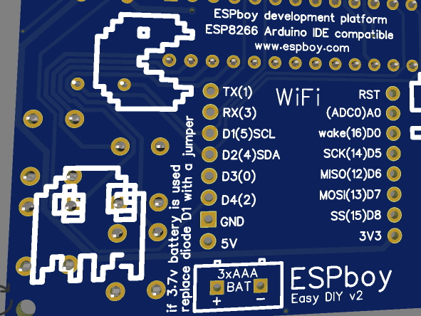
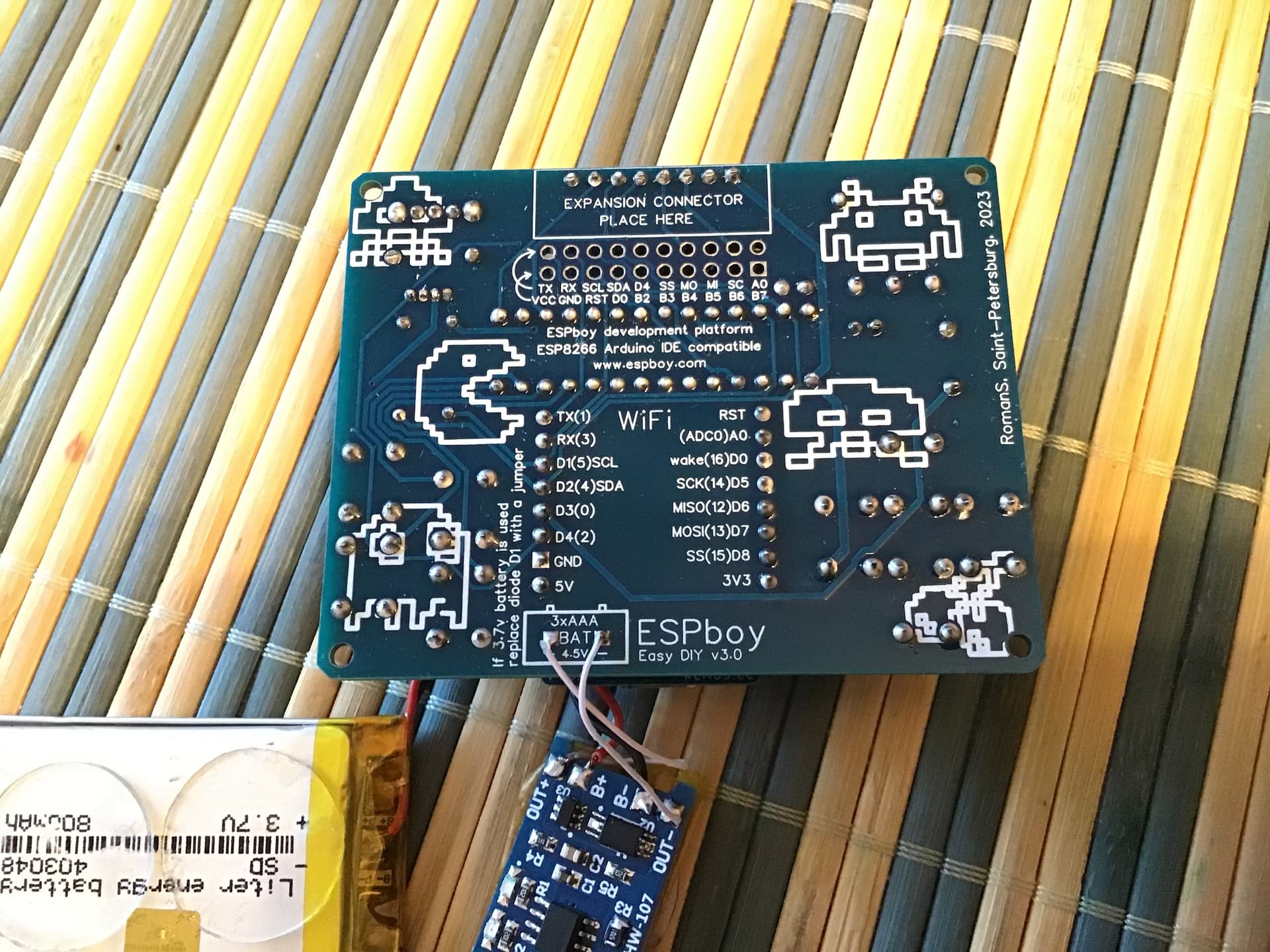
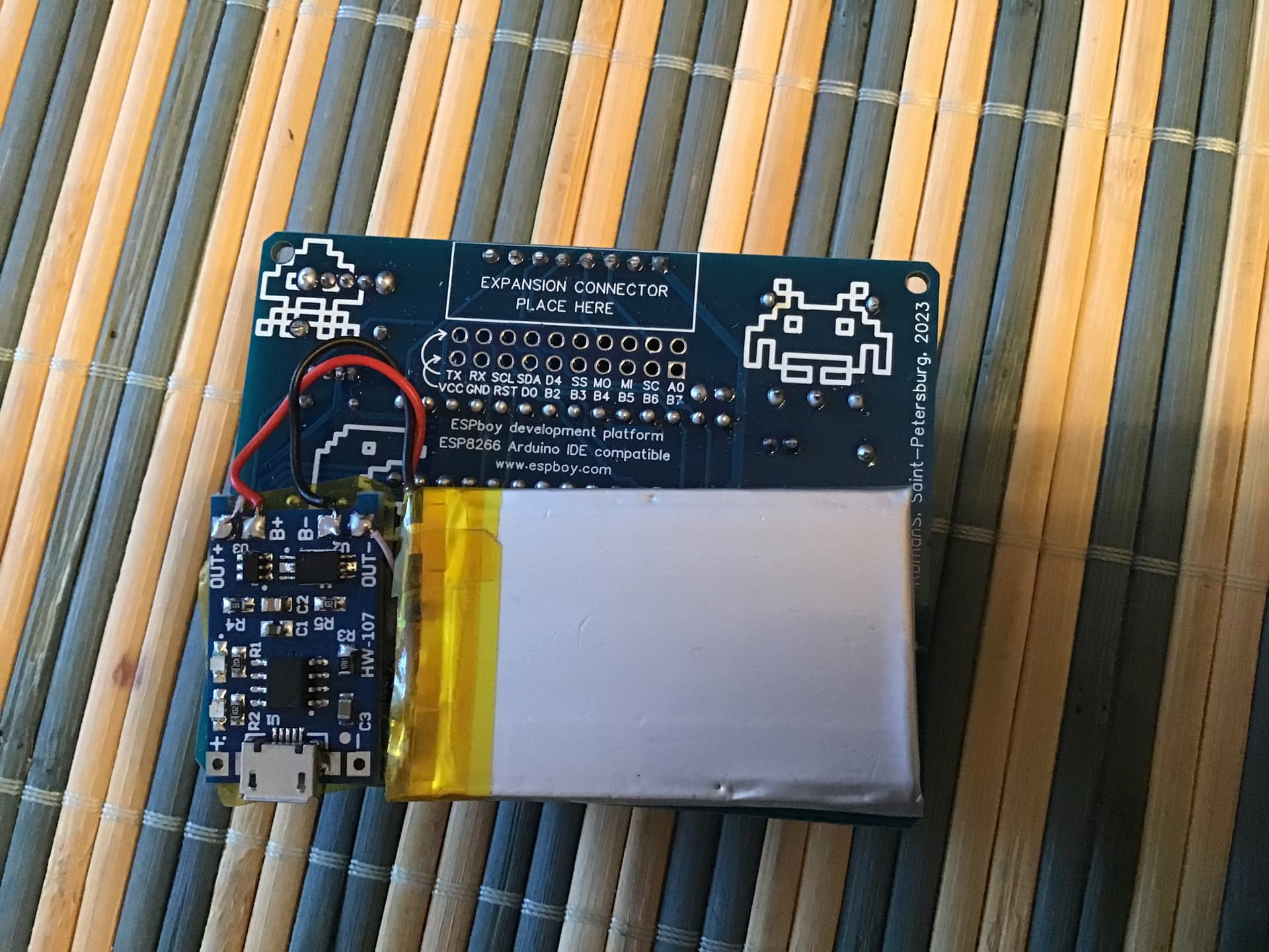
Note that if you want to power the board using 3 NiMH rechargeable batteries (~3.6V total) or a 3.7V LiPo battery, instead of 3 Alkaline or Zinc-Carbon batteries (~4.5V total), you should replace diode D1 with just a wire jumper to provide the proper voltage on the expansion header’s VCC pin.
Hello!
You can try it and tell us about the result )
my goal was to use as few elements as possible with all the large components with mounting through holes.
but anyone can make their own circuit
If you supply power by putting a full 5V on the battery connections, it would be better to put two regular diodes in series for D1 instead of a single one.
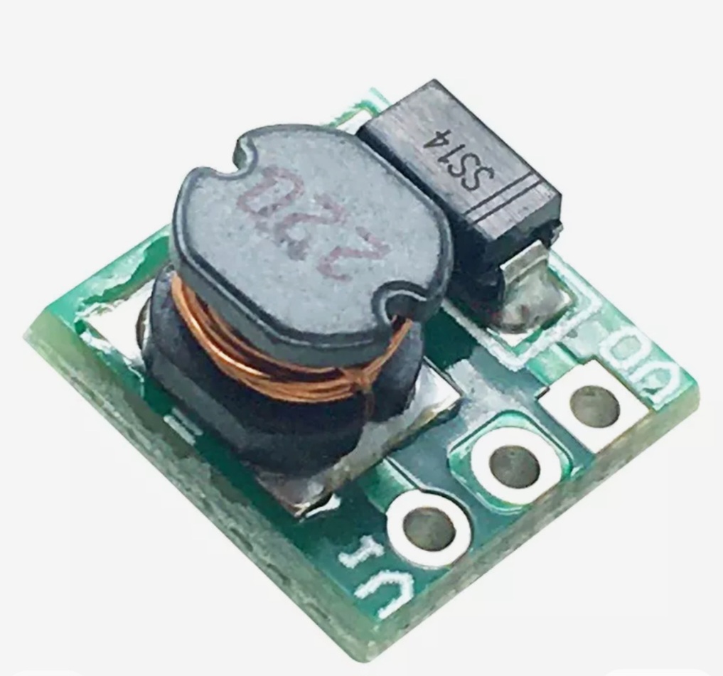
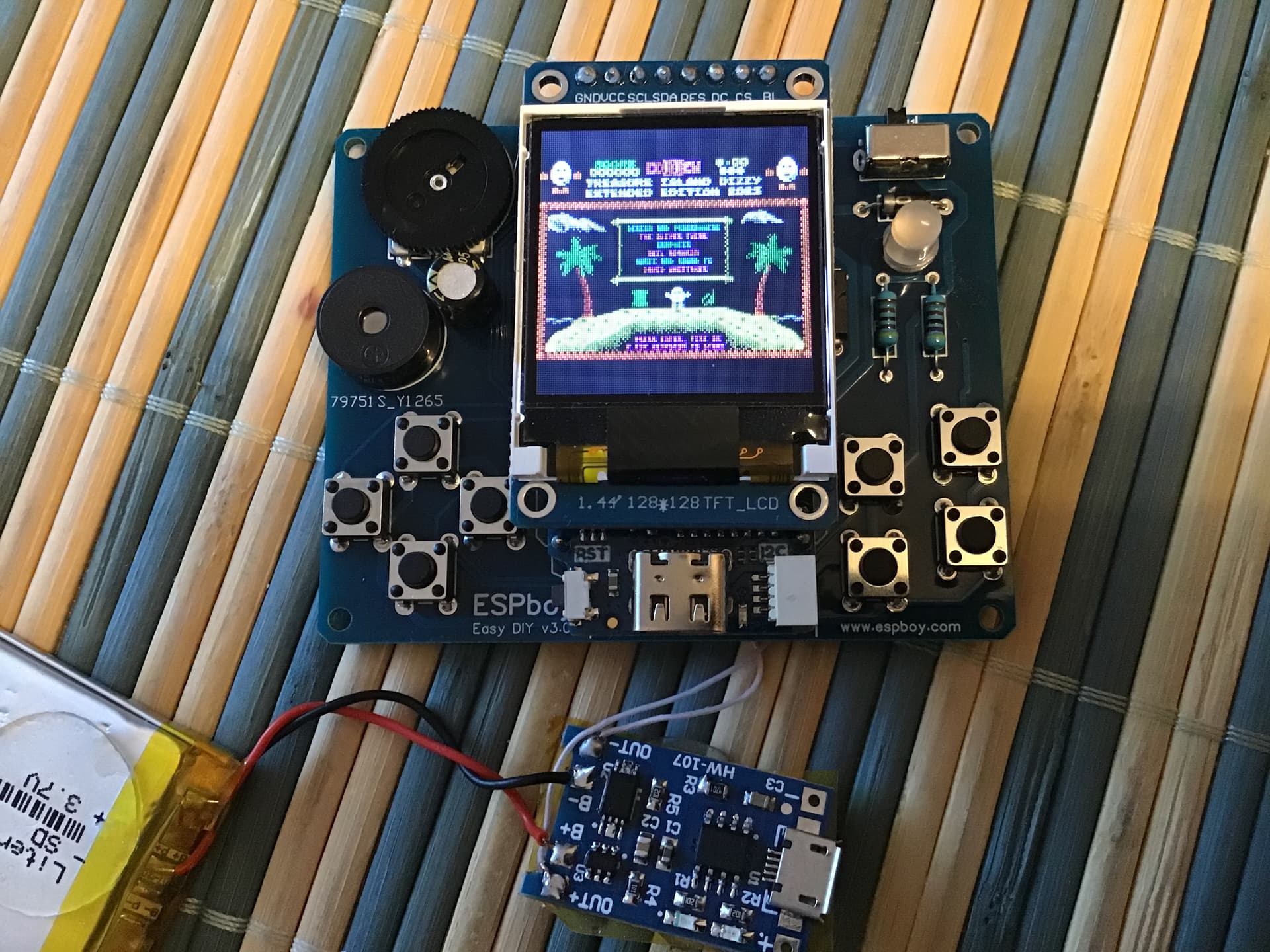
Also, you should put the booster module after the power switch, so the booster isn’t receiving power even when the switch is off.
NOTE! @RomanS found some problems with the V2 board that my modified board is based on. Until I update my schematic and PCB to match whatever fixes are implemented in the original, it is recommeded that you don’t use my board.
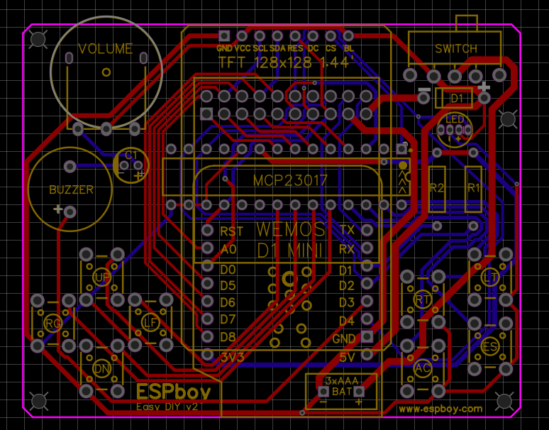
It’s good practice to have decoupling/bypass capacitors close to the power pins of the components on a PCB. The Wemos module will have it’s own capacitor(s) on board but it would be good to have one for the MCP23017 chip. I’ve added this capacitor. The capacitor should be a 0.1uF (or higher) ceramic.
In addition, I reversed the buzzer pins so that the “+” pin now goes to the V_BAT side of the circuit, which makes more sense to me but it won’t make a difference electrically.
I then got enthusiastic and made a large number of changes to the trace routing and widths, as well as a few changes to the silkscreens. However, other than the new capacitor, it should be identical to the original, electrically and for component placement.
NOTE that if there are any errors or problems with the original schematic or PCB then it’s very likely they exist in this version, as well.
Here are the details of what I’ve done:
On the schematic and PCB add a decoupling capacitor for the MCP23017.
On the schematic and PCB changed the buzzer polarity so plus (+) now goes to the V_BAT side.
Removed unused via in GND trace close to the BAT- pad.
Removed unused via in the D4_LED trace.
Made all trace vias have a 0.4mm hole and either 0.8mm or 1.0mm diameter.
Moved, rerouted and resized many traces to:
Add more clearance from component pins.
Add more clearance around board mounting holes.
Move traces away from the edge of the board.
Make thicknesses more consistent and in some cases wider for power traces.
Moved bottom silkscreen B5 and B7 expansion connector text, and reduced the size of and repositioned B6 and SC text due to interference with the new capacitor pads.
On top silkscreen changed text for the display from 1.44’ to 1.44" (feet to inches).
On top silkscreen changed position of text for the display to avoid printing on top of a new via.
On bottom silkscreen changed text “EXPANSION SLOT” to “EXPANSION CONNECTOR” and repositioned the text to avoid printing on top of new vias.
On bottom silkscreen for the text describing substituting a wire for the diode, changed the “I” in “If” to uppercase.
On both silkscreens moved “ESPboy” text up a little and changed the version to v2.1(MLXXXp)
Hello Roman! Very interested in this poject and really like to buy this kit in Russia for my children. Just found AliExpress official(?) store “ESPboy store” but it sells prebuilt ESPboys only. Is there any chances to order this kit in Russia?
Hi!
I think I have enough parts for one such kit.
Write me a private message here on the forum or in the Discord of the project (links here www.espboy.com) and we’ll decide how best to handle this deal .
Hi Roman. I submitted payment through paypal. Please let me know if you received it or if there are any issues. Thanks Roman! Cant wait to buid this beast
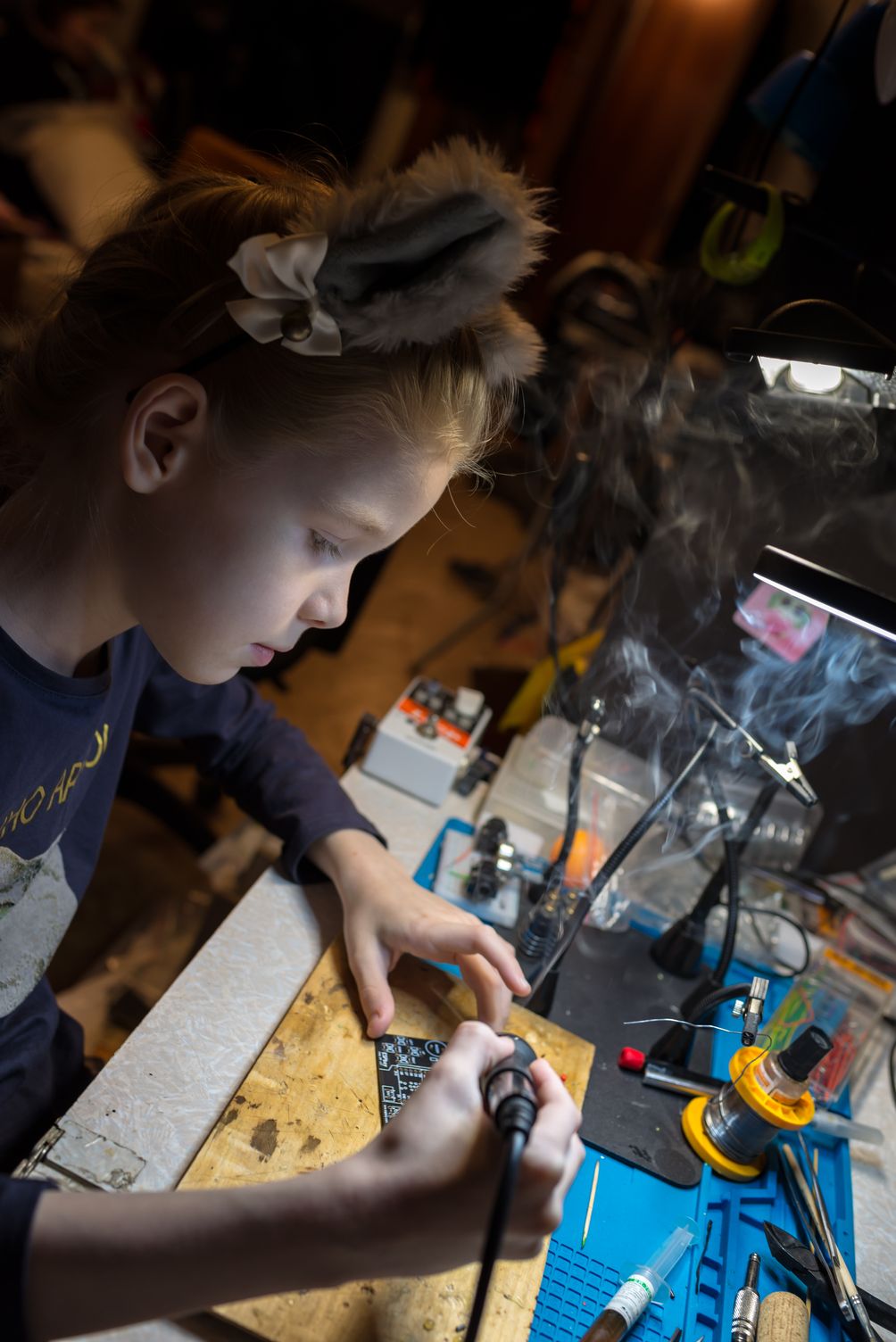
About 4 weeks ago my 9 y.o. daughter asked me to teach her soldering (she just saw me soldering guitar pedals and other DYI stuff). I started to looking for a simple DIY-kit for her but she only wanted a game console kit. I found out that it is very difficult to buy such kit in my country, it can be obtained from abroad (Chinese online markets), but with no info and games support, libs and intelligible specs. Thus I found ESPboy and its community.
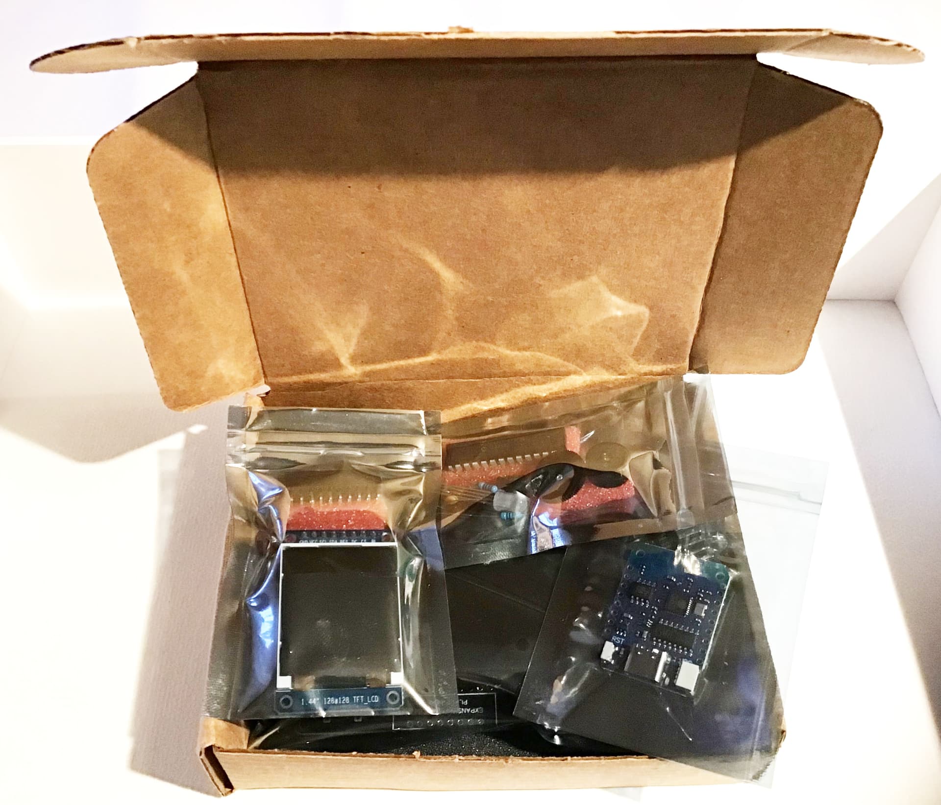
ESPboy author was kind enough to send me a ESPboy:kit v3.1 over local mail and we got it in late November. Just leaving my first impressions here:
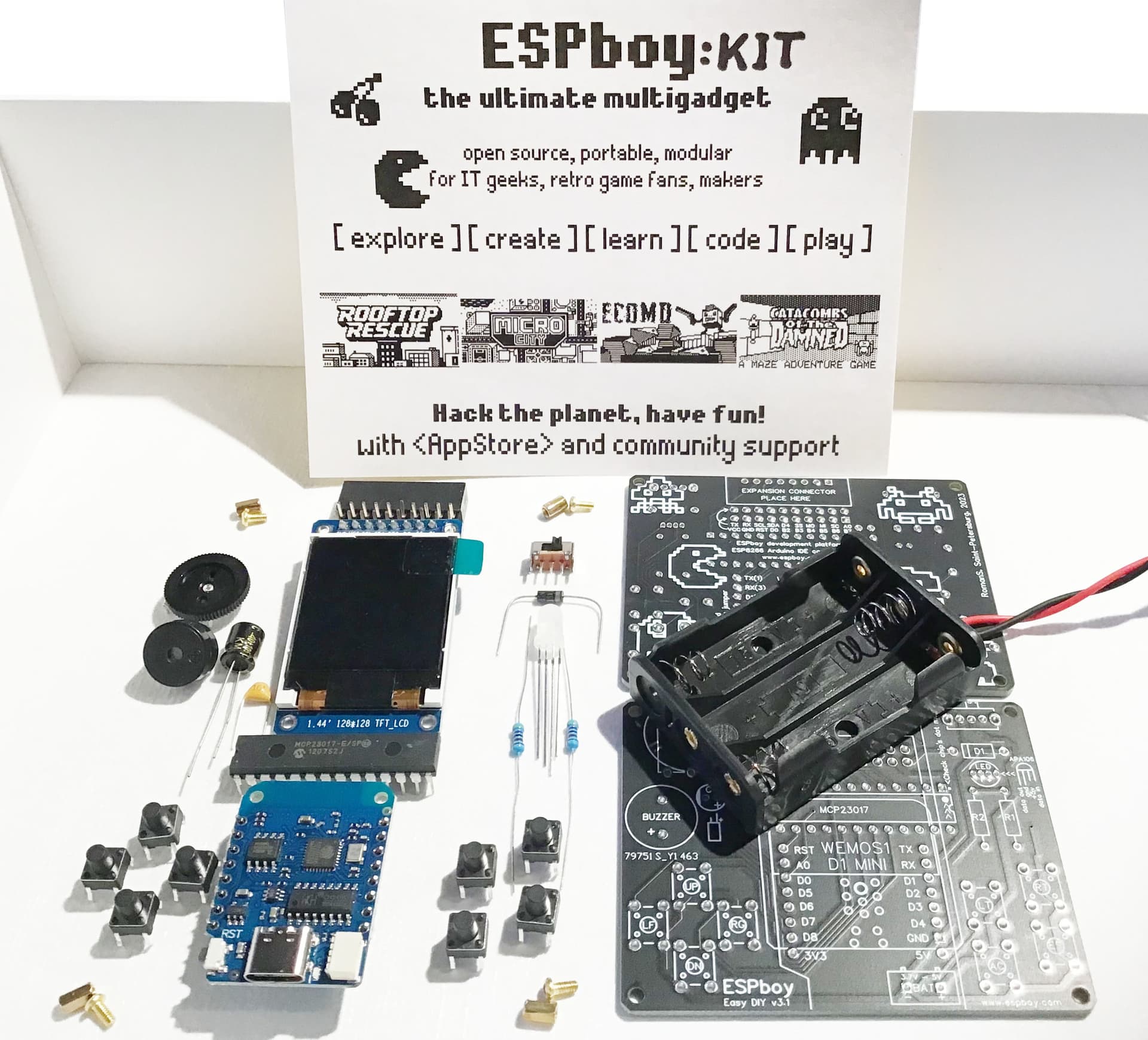
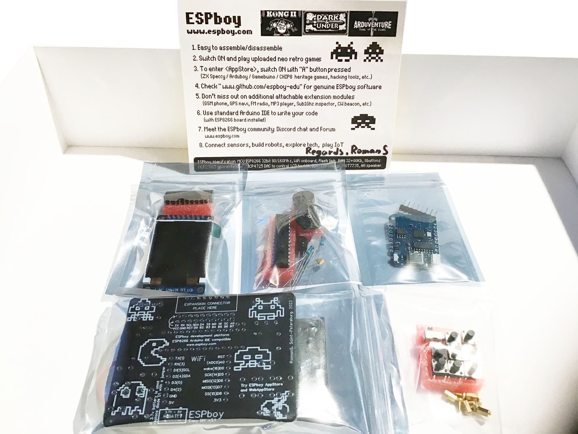
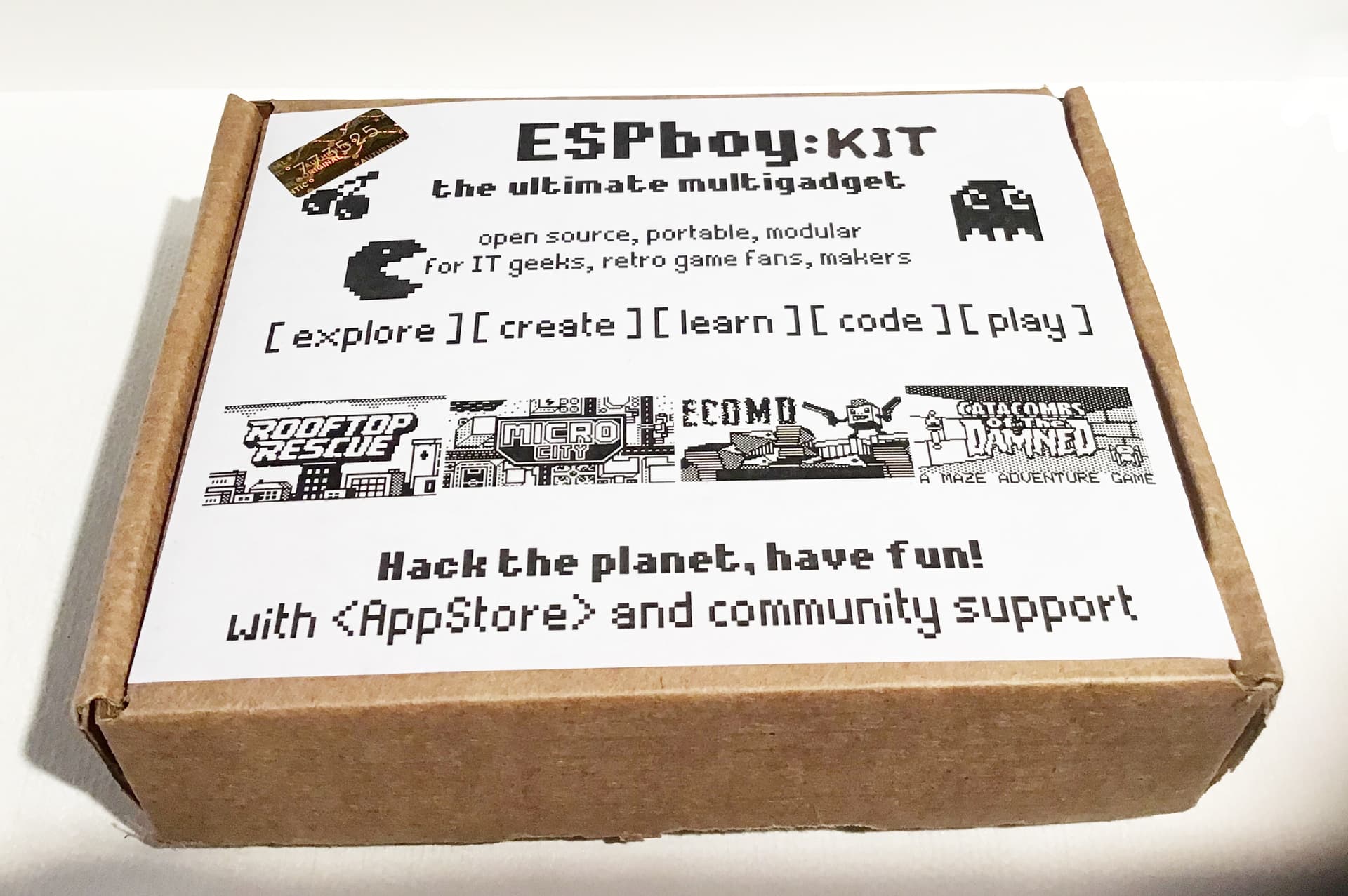
Kit comes in a cute gift box, all elements safely inserted into foam pads.
it has very high quality main PCB - simple to solder even for a child. Cool silkscreen printing on PCB, my daughter likes Pac-Man eating soldering holes).
There are TWO same main PCBs! It’s an awesome trick - a spare PCB and a blackplate of console at the same time.
MCP23017 chip, screen module and ESP board solder directly into main PCP (no panels). It’s not so comfortably for soldering and repairing, but it will works more reliably and console can be thinner.
Some suggestions for project:
In v.3.2 (if it is) do more reliable and useful DIP-buttons 12х12х7mm (with X-shaped stocks for caps)
We started to assemble kit and now we have all buttons, connectors and MCP23017 soldered (we can do it only on weekends unfortunately). In a week or two we are planing to finish it).